Marking method for couplings and key connection is as follows:
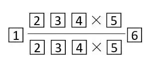
Among, 1 is the model and name of the couplings; 6 is the standard number; The middle numerator and denominator are respectively marked with the corresponding code and size of the main and driven end; 2. Mark shaft hole form code; 3 marked keyway form code; 4 mark shaft hole diameter; 5 mark shaft hole matching length; If the shaft hole and keyway form and size of the main and driven ends are the same, only one end is marked in the center, and the other end is omitted. Y type shaft hole, A type keyway code omitted in the mark is not written.
- If it is rectangular spline hole connection: 2, 3 and 4 are marked according to the requirements of GB/T1144-2001 Rectangular spline;
- If it is cylindrical straight gear spline connection: 2, 3, 4 according to GB/T3478.1-1995 provisions mark;
- Expansion sleeve connection: 2, 3, 4 according to JB/T7934-1999 provisions mark;
- Hydraulic handling connection: 3 is not marked because there is no keyway.

Example 1: UL5 tyre coupling active end: Y-type shaft hole, A-type keyway, D1 =28mm, L=62mm. Driven end: J1 axle hole, B keyway, D2 =32mm, L=60mm.
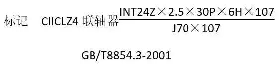
Example 2: CIICL4 drum gear coupling driving end: cylindrical straight involute spline hole, number of teeth 24, module 2.5mm, 30° flat root, tolerance grade 6, L=107. Driven end: J axle hole, A keyway, D =70mm, L=107mm.
Model in the mark consists of group code, variety code, form code, specification code and specification code;
The nominal torque Tn of the coupling is designed according to the serialization requirements. Each specification couplings long - term transmission of the main parameters. Its specification is in accordance with GB/T321-2005 "Priority number and Priority coefficient" R5, R10, R20;
Values of series 1 [in order of R5 from (0.10 to 1.6) ×106] shall take precedence over those of Series 2 [in order of R10 from (1.0 to 2.0) ×106]. The values of series 2 should take precedence over those of series 3 [arranged R20 from (1.0 to 2.0) ×106].
The nominal torque value shall conform to the provisions of GB/T3507-1983.
Couplings Shaft Hole form and standard
Shaft hole form of the coupling mainly depends on the form and size of the connected shaft. In the selection of coupling, according to the transfer torque size, structure, determine its shaft hole form. The shaft holes shall conform to the shaft extension standards GB/T756-1990, GB/T757-1993, GB/T1569-1990 and GB/T1570-1990.
Shaft hole form and size of the coupling should generally comply with the provisions of GB/T3852-1997.
There are seven types of shaft holes in the coupling:
- They are long cylindrical shaft holes (Y type).
- A short cylindrical shaft hole with a countersunk hole (J type).
- Short cylindrical shaft holes without countersunk holes (type J1).
- Long conical shaft hole with countersunk hole (type Z).
- Long conical shaft hole without countersunk hole (type Z1).
- Short conical shaft hole with countersunk hole (type Z2).
- Short conical shaft holes without countersunk holes (type Z3).
Through this article, you can understand marking method for couplings. This marking method suitable for all of our jaw couplings and gear couplings product.
Attention please:
