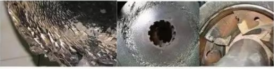
Cavitation phenomenon: when the liquid enters the first stage impeller of the pump, the static pressure is lower than or equal to the saturated vapor pressure at the temperature, the liquid vaporizes and produces bubbles. With the liquid flowing into the higher pressure, bubbles suddenly condense, and the surrounding liquid rapidly concentrates, resulting in hydraulic impact. This vaporization and condensation produce pump erosion, vibration and performance decline phenomenon, commonly known as cavitation phenomenon.
Pump installation sequence: technical preparation → foundation acceptance → unpacking inspection → equipment lifting in place → primary leveling alignment → secondary irrigation impeller → fine leveling alignment → secondary grouting → centering of pump and motor jaw coupling → process pipeline installation → centering and stress review → trial preparation, single test → load test → delivery and acceptance.
Please note: if it is a large flow pump, the pump speed is very low, the reducer power is large. Low speed gear couplings are also available.
Precautions: The inside of the pipe connected to the device should be cleaned. The fixed welds should be far away from the equipment. No additional forces are allowed to be applied to the equipment. Temporary blind plates should be added to the inlet and outlet of the equipment, which can be removed after the pipes are blown clean. The flange spacing should be the minimum distance that can be put into the gasket smoothly. When the pipe is finally connected, the radial displacement should be monitored with a dial gauge on the coupling. When the rotational speed is less than 6000 RPM, the displacement is less than or equal to 0.05mm. When the speed is greater than 6000rpm, the displacement is less than or equal to 0.02mm. Otherwise, adjust the pipe.
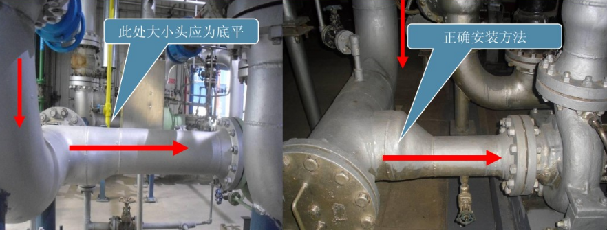
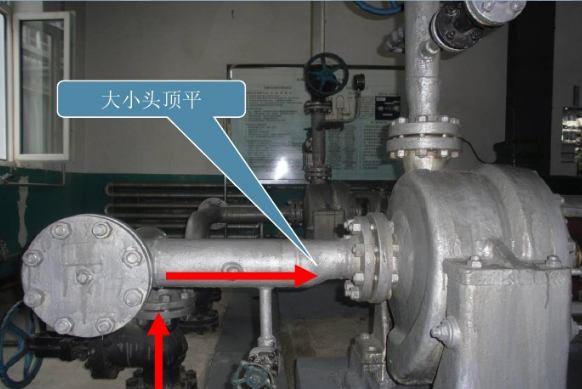
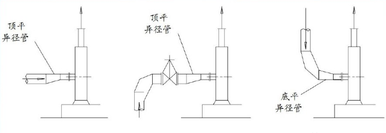
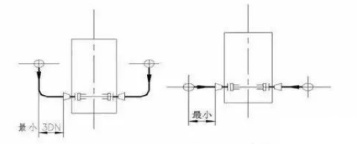
When stainless steel gear pump inlet pipe system has reducer pipe, the pipe diameter ≥DN65 uses eccentric size head to prevent gas accumulation at reducer. The installation side of the reducing pipe is shown in the figure, that is, when the front elbow of the inlet flange is downward, the reducing pipe is flat on top; When the elbow is up, the bottom of the reducer is flat.
Site installation display: media from top to bottom
On-site installation display: media from bottom to top
Stainless steel pump inlet should be set up a section of not less than 3 times the pump inlet pipe diameter long straight pipe section, large pump should be 7 times the pump inlet pipe diameter above the straight pipe section, in order to make the liquid smoothly into the pump, avoid deflection and rotating flow, cause pump vibration and noise.
Stainless steel pump piping for the upper suction, do not have to consider the suction inlet requirements of the straight pipe section. Vertical pipe can be directly connected to the suction pipe mouth through elbow and reducing pipe, as short as possible.
When the inlet and outlet of the centrifugal pump are on the same vertical surface, in order to facilitate the installation of the valve, the inlet and outlet can be used to increase the distance between the inlet and outlet pipes by eccentric reducing pipe or two 45° elbow.
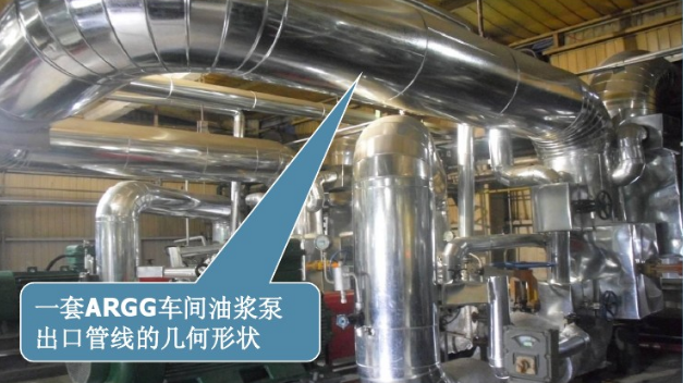
Pump outlet and deep protection pipeline design:
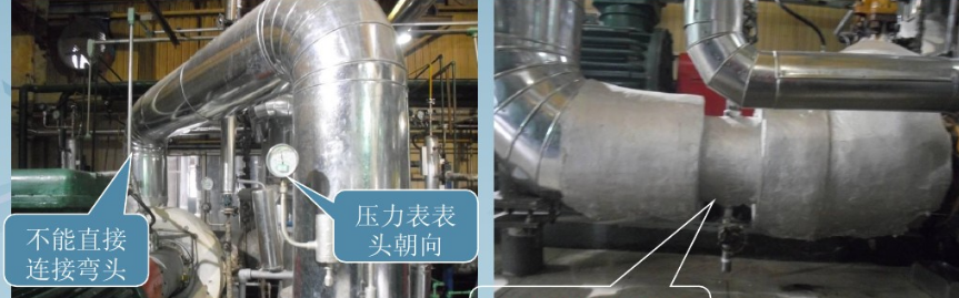
Pump outlet should not be directly connected to the elbow. Drain valve between the cut-off valve and check valve at the pump outlet. The pump outlet pressure gauge is installed on the nipple between the pump port and check valve, and can also be installed on the outlet reducer. Pressure gauge nozzle should have a root valve, pressure gauge head toward the operating surface.
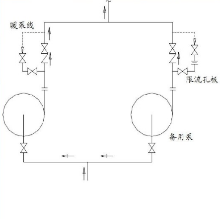
Protection pipeline of pump -- pre-hot wire: when the temperature of pre-hot wire conveying medium is greater than 200℃, to avoid the rapid influx of high-temperature liquid into the pump to be operated when switching hot oil pump. So that the pump body, impeller heat uneven damage or deformation, resulting in the fixed part and rotating part of the stuck phenomenon, so that the need to set up a pre-hot line, so that the outage of the pump to maintain the starting state, in order to switch at any time.
The protection pipeline of the pump
small flow line: when the working flow of the pump is less than 30% of the rated flow of the pump, it will produce a force perpendicular to the axis - radial thrust. Moreover, because the pump operates at low efficiency, the liquid temperature of the inlet part rises high, the steam pressure increases, and cavitation is easy to occur. In order to prevent cavitation, the small flow line should be set up for the normal operation of the pump at the lowest flow rate.
Pump protection pipeline
balance line: for conveying liquid in bubble point state under normal temperature saturated steam pressure high dry atmospheric pressure liquid, in order to prevent the liquid into the pump to produce steam or bubble into the pump to cause cavitation, generally appropriate balance line. The balance line is the gas phase from the pump inlet to the suction tank (tower).
Pump protection pipeline
Bypass line: start the high lift pump, the outlet valve unilateral pressure is too large, not easy to open, if forced to open, there will be damage to the valve stem, valve seat risk. A bypass line with a limited orifice plate is set before and after the outlet valve for easy opening. At the same time, the bypass line can reduce the vibration and noise of the pipeline.
