Use and characteristics of the coupling
Couplings used to join the two shafts together. A device that engages or separates a machine after it has stopped running by transmitting motion and torque.This article is mainly about how to choose couplings?
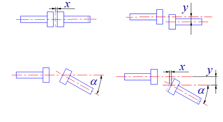
Due to manufacturing and installation errors, deformation after load bearing and the influence of temperature change, the two shafts connected by the coupling can not ensure strict alignment, but there is a certain degree of relative displacement. This requires that when designing the coupling, different measures should be taken from the structure to make it adapt to a certain range of relative displacement.
Couplings Type and usage - How To Choose Couplings Types
1. Fixed couplings (rigid couplings)
Relative displacements between the connected two axes have no compensation ability, so the neutral requirements of the two axes are high. When the two axes have relative displacement, additional loads will be imposed in the structure. The structure of this kind of coupling is relatively simple.

Fixed coupling is the use of fastening bolts to fix the shaft, which is the most traditional, the lowest cost of fixing, but the front end of the bolt and the shaft direct contact. May cause shaft damage and disassembly difficulties.
The most common fixed coupling: sleeve coupling, flange coupling, clamp coupling.
Commonly used fixed coupling: sleeve coupling, clamp coupling.
2. Movable coupling (elastic coupling)
It is mainly used for two shafts with deflection or relative displacement in the work. According to the method of compensating displacement, it can be divided into rigid movable coupling and elastic movable coupling.
2.1 Rigid movable coupling
Rigid movable coupling: compensated by the degree of motion in one or more directions of the dynamic connection formed between the working parts of the coupling.
Common portable rigidity coupling: tooth coupling (allows the axial displacement), cross grooved coupling (used to join two axis parallel displacement or angular displacement is very small), universal shaft coupling (for two axis with oblique Angle or at work have larger angular displacement), gear coupling comprehensive displacement (allow), chain coupling (radial displacement is allowed).
Commonly used rigid movable coupling: cross groove coupling, cross slider coupling, universal coupling.
2.2 Flexible movable coupling
Elastic movable coupling: the deflection and displacement of the two axes are compensated by the elastic deformation of the elastic element, and the elastic element also has the performance of buffering and damping.
Common elastic removable coupling snake spring coupling, radial multi-layer plate spring coupling, elastic ring bolt pin coupling, nylon bolt pin coupling, rubber sleeve coupling, plum coupling, diaphragm coupling and so on.
Commonly used elastic removable coupling: plum coupling, diaphragm coupling.
Fixing method of the coupling
There are several common ways to fix the coupling:
Positioning screw fixation: it is a traditional fixation method to lock the fixed shaft with a gap of 90° between two positioning screws. Because the front end of the screw is in contact with the shaft, it may cause damage to the shaft or difficult to disassemble.
Keyway type: this type is the same as the positioning screw type, which is the most traditional way of fixing. It is suitable for high torque transmission. In order to prevent axial sliding, it is usually used with the positioning screw type and clamping screw type.
Choose process of coupling
Type Selection
4.1 Two-axis alignment:
Strict alignment -- fixed coupling
There is no guarantee of displacement during strict alignment or operation -- flexible coupling
When zero back clearance is required, choose diaphragm type or groove type
When high torque is required, diaphragm type, cross type and plum type are selected
Servo motor with diaphragm type, stepper motor is more groove type
Cross is often used for cylinder or membrane motor occasions, slightly less precision performance (not high requirements)
4.2 Load condition
Load stable or little change -- rigid coupling
Frequent starting brake or load variation - flexible coupling.
4.3 Speed: working speed < the allowable speed of the coupling
Low speed -- rigid coupling
High speed -- flexible coupling
4.4 Environmental conditions
Low ambient temperature (<-20℃) or high (>45℃) should not be used with rubber or nylon as elastic elements of the coupling; Consider mounting dimensions.
4.5 Coupling shaft selection process
According to the load condition, first roughly choose a type.
Calculation of coupling torque (T electrical ≥ T connection).
Determination of eccentricity, allowable size of space and other conditions (eccentricity: angular deviation, axial deviation, radial deviation).
Select the specific model according to the torque size, eccentricity and space allowable size.
Finally determine the size of the shaft holes at both ends (the size of the shaft holes at both ends can be different).
Related products:ML Jaw Flexible Copling